26. Differential
- tiggr
- Jan 11, 2023
- 3 min read
Updated: Apr 6, 2023
Diff = Difficult!

The engine hoist was setup to lift the differential unit using a pair of ratchet straps. It took some time to get to the point where the differential was correctly balanced and stable. The wooden floor in the boot area was removed and the webbing straps passed up to the engine hoist. The differential was lifted into position - a push was required to get the bracket to sit correctly between the bosses.
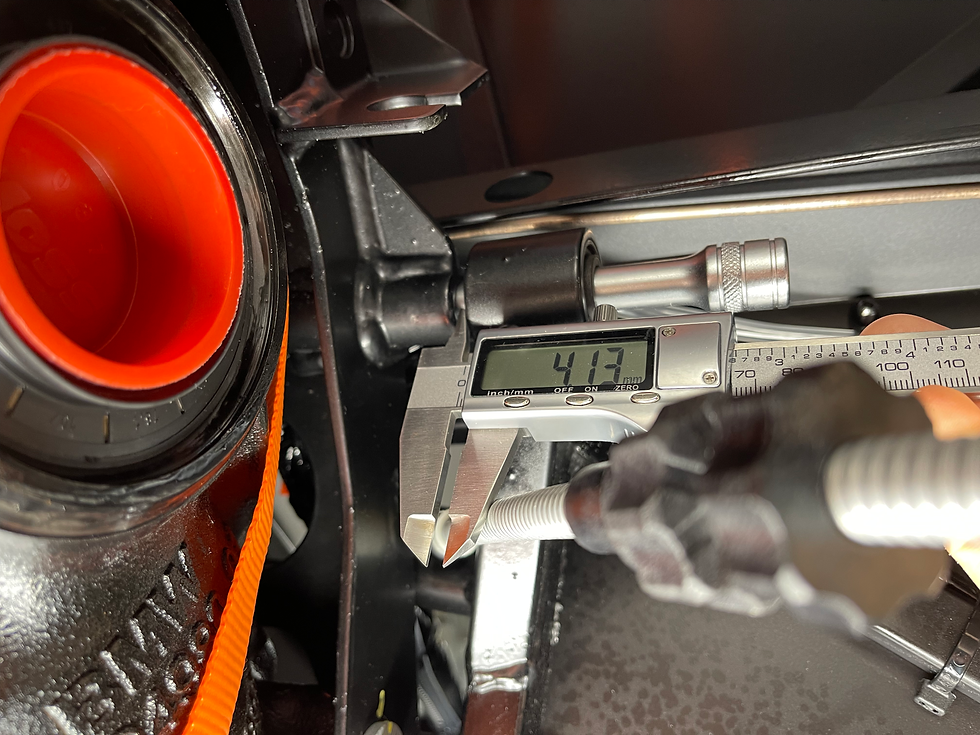
The differential was manoeuvred so that it was flush with the left hand boss, and then the resulting gap on the right hand side was measured with verniers. This allowed a quick decision of what washer and shim combination would be needed for the upper and lower bolts (upper = one large + one medium; lower = one medium + one shim). Measuring various washers / shims allowed an almost exact match with the required gap due to the part to part variation in thickness.

Shining a strong torch light into the lower right hand bolt hole showed it was reasonably well aligned and so the washers and bolt was fitted to finger tightness and then fully tightened - this pulled the differential over to the right hand side. A screwdriver with a magnetised tip was very helpful in manipulating the washers.
Using the same process on the lower left hand bolt, it was possible to see that the differential was sitting low relative to the chassis hole. The lifting jack was positioned below the differential and used to finely adjust the position until there was a clear line of sight through the holes. The washers and bolt were fitted.
Using the same technique of shining a torch into the upper bolt hole, it looked clear and aligned. Plenty of CopperSlip was applied to the bolt and it was slid through the chassis bush and into the differential. About a third of the way in, the bolt became very stiff and not possible to move manually. A deadblow was used to knock the bolt through the differential until the tip of it could be seen through the left hand bush. At this point and inspection through the left hand upper hole showed that the bolt was emerging from the differential a good 2mm to the right of the chassis bush.
Over the next hour, various methods of loosening or even removing the lower bolts, applying pressure to the side of the differential produced no change in the position of the top alignment. I then noticed that the top rails of the differential cage were pressing hard against the cross rail that supports the boot. This is a non-structural aluminium rail through which the fuel line passes - but it was definitely preventing the differential from getting high enough and secondly I was concerned about vibration from the differential being conducted into the chassis.

The differential was lowered (with the lower two bolts still in place) sufficiently to allow two small recesses to be cut into the cross rail and prevent contact with the cage.
Marking and cutting the cross rail - differential
When the differential was raised again, the alignment was better and the upper bolt was fitted, washers in place, with the help of a deadblow. The lower and upper bolts were then torqued to 61Nm and 81Nm respectively. Finally the propshaft was bolted finger tight (for now) to the differential.

The LSD oil (800ml) was added in the usual way - a gravity fed pipe and funnel arrangement through the Boot Floor opening.
Post-PBC Update : I used exactly 800ml of differential oil but the PBC feedback explained that when the Diff first rotates it can draw up a good amount of oil and it should then be topped up to the level of the filler plug. Please see here.


Comments